Interactive training visualization of a preloaded bolted joint under external tensile load
Background & theory
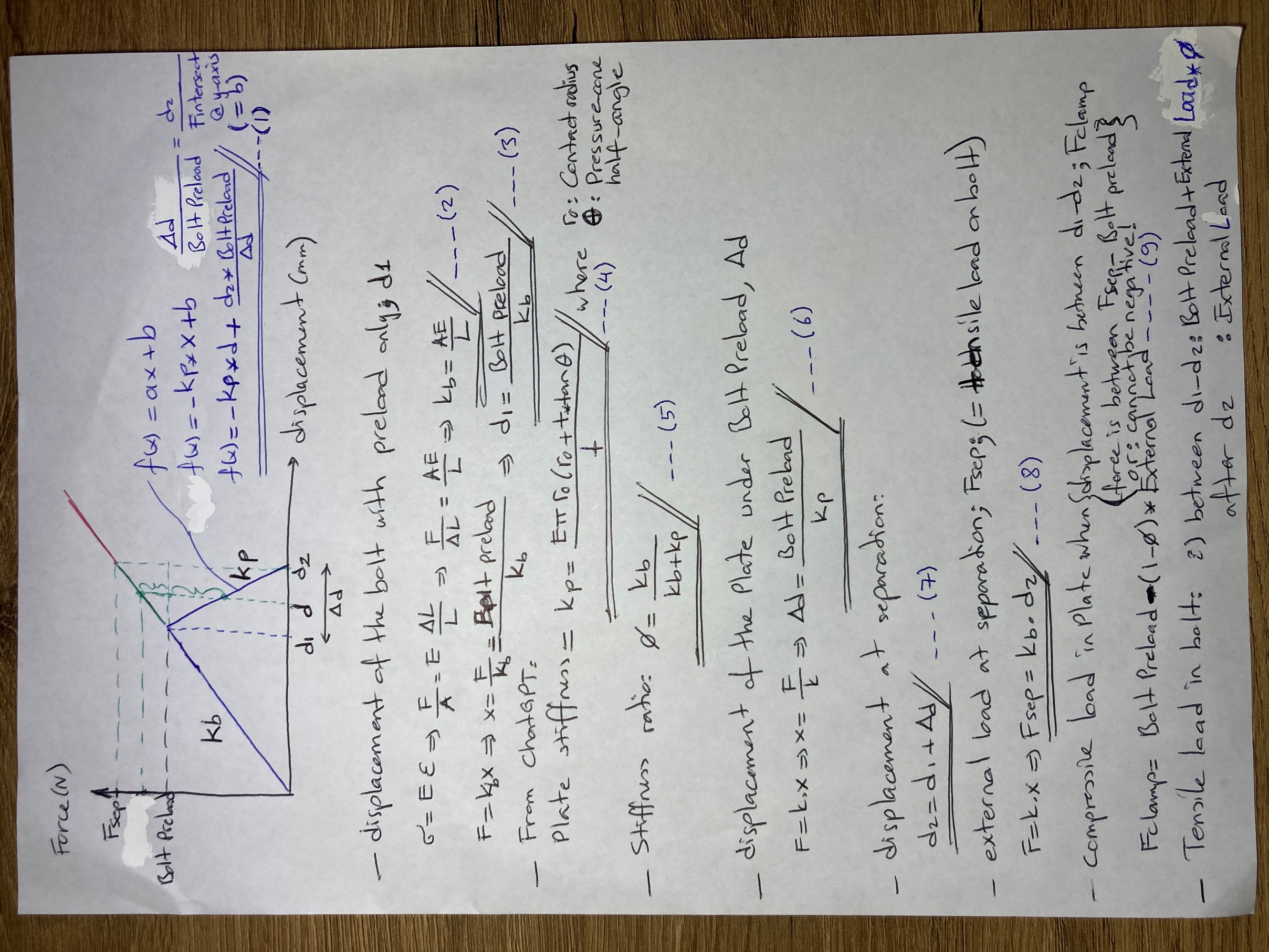
A preloaded bolted joint behaves like two springs acting in parallel on the same fastener: the bolt itself, stretched in tension by the preload, and the clamped members (plates, flanges, gaskets), compressed by that same preload. Both stiffnesses matter, because they decide how an external tensile load applied to the joint actually gets shared between "more bolt tension" and "less plate compression."
kbolt = A·Ebolt / L (simple axial stiffness of the bolt shank)
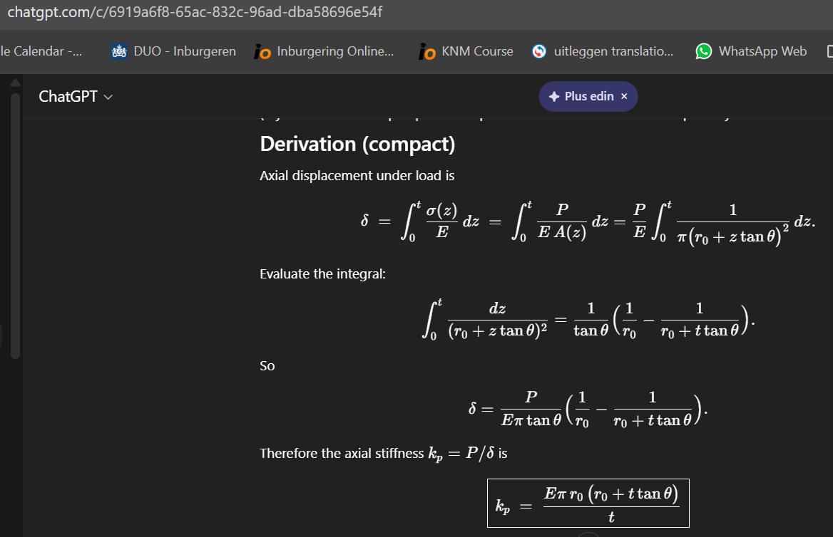
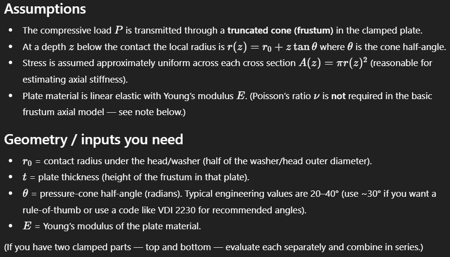
kplate — from the pressure-cone method: the compressed material is modeled as a hollow cone of half-angle α spreading out from the bolt head/nut, integrated through the grip length to get an equivalent stiffness
Those two stiffnesses combine into a single number that governs everything else — the stiffness ratio:
φ = kbolt / (kbolt + kplate)
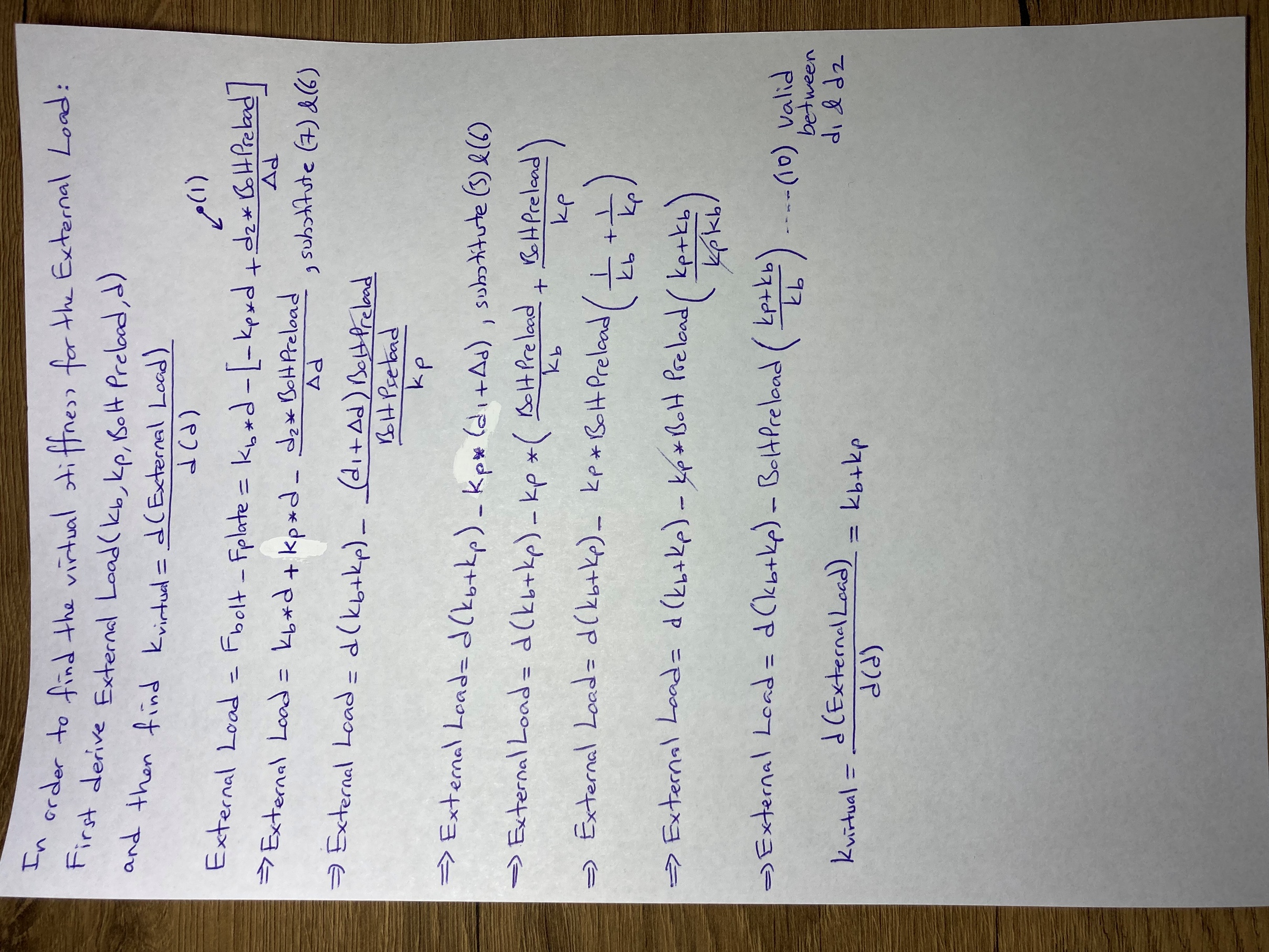
As long as the joint stays clamped (some compressive force remains in the plates), an external tensile load Fext increases the bolt's tension by only φ·Fext — the rest is simply relief of the plates' compression, not extra bolt load. This is the whole point of preloading a joint: a stiff bolt in a relatively soft joint (small φ) is largely insulated from fluctuating external loads, which is exactly why preload is central to fatigue-resistant bolted design.
That protection has a limit. As Fext grows, plate compression keeps dropping until it reaches zero — the separation load. Beyond that point the members are no longer clamped together at all, and the bolt abruptly starts carrying the entire external load directly, not just its φ share. This tool solves for bolt load, remaining clamp force, joint stiffness ratio, and the separation point directly, and flags whether the joint you've defined stays clamped or separates under the load you specified. The derivation of the pressure-cone stiffness method is shown step by step in the "View calculation / theory" images above.